Hardware overview
(Note: for a more detailed hardware overview, please see the project documentation section)
MIDI interpreter and FPGA hardware
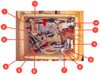
1.Roland UM-1 USB MIDI controller
2.Gumstix Control hub
3.Generic USB MIDI controller
4.Power input
5.Line in/out ports
6.MIDI in port
7.Parallel JTAG input (for reprogramming FPGA whilst the synth is still inside it’s box)
8.Ethernet I/O
9.USB hub
10.Controller for built in surface
11.12V-5V rectifier & down converter for control surface and FPGA
12.Serial communications link to FPGA
13.Built-in surface pots (x8)

The gumstix verdex embedded computer system: The heart of MIDI interpretation and GUI control of the synthesizer.
analogue systems

View of the analogue systems (breadboard implementation. Schematics and layout available soon...)
Hardware used is as follows:
1. 8 bit DAC08EN - Audio signal
2. 8 bit DAC08EN - VCA Control Voltage
3. 8 bit DAC08EN - VCF Control Voltage
4. 8 bit DAC08EN - Res. Control Voltage
5. ICL7660 (used to create -5V from 5V)
6. ICL7660 (used to create -5V from 5V)
7. AD633 Mixer - Line-In (vocoder)
8. ADG409 Multiplexer (turn on/off vocoder)
9. CEM3389 (signal processing chip)
10. OpAmp (output amplification)
11. AD633 Mixer - Filter - (filter modulator)
12. Invertor (used to convert TTL for 7660)
13. ADG409 Multiplexer (turn on/off modulator)
System Architecture
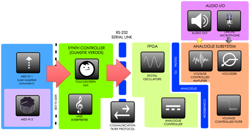
The system was designed in modules according to the above diagram. It’s main components were grouped into functional blocks:
MIDI Input
Allows MIDI compliant devices to be connected to the system using a standard 5-pin DIN connection. Additionally, this is where the systems inbuilt control surface is connected.
Synth Controller
Interprets MIDI input and provides the system’s touchscreen user interface. Its key role is to convert MIDI input into system control signals and graphical events pertaining to the synth’s audible functions, and distribute them across the serial link to to the relevant synth module (e.g. conversion of MIDI note signals into to frequency control vectors to be sent to the FPGA). The synth controller also provides the high level, time-based audio control functionaliy. It is responsible for effects such as Envelope generation.
Serial Link
The serial link connects the Synth Controller and the FPGA. It consists of a physical connection between the devices, as well as an optimized communications protocol to enable the setting of synth parameters such as oscillator frequencies, and analogue systems control parameters.FPGA
The heart of audio control systems and sound generation. The FPGA is responsible for oscillator function generation, mixing, and basic audio synthesis in the digital domain. It also provides digital control for settable analogue parameters, as well as digital-to-analogue conversion of the audio signal prior to analogue processing.Analogue Systems
Provides core audio post-production functionality and is controlled by the FPGA. The analogue systems consists of various mixers, ICs, and DACs (for audio and control signals. It’s key components are a voltage controlled filter, a voltage controlled amplifier, and a vocoder.
